The basic structure of a PEM fuel cell is relatively simple (see Fig. 3). It consists of two electrodes that are separated by a membrane. On the anode side, the energy source hydrogen is supplied as fuel and on the cathode side, oxygen from the air is supplied as an oxidizer. The membrane itself is coated on both sides with catalyst material. This ensures that electrons are split off from the hydrogen molecule on the anode side. The membrane is permeable to the resulting protons, so they can pass through and make it to the cathode side, in order to be able to react there with oxygen from the air to form water.
The electrons that split off on the anode side travel to the cathode via a closed electrical circuit. Used in this are the electrical as well as thermal energy. In a vehicle, this electrical energy can then be used, for example, to charge a battery or directly for the electric drive. In the stationary area, for example for the self-sufficient energy supply of a house or building complex with electricity and heat, the fuel cell ensures emissions-free living with renewable energies. When used to secure critical infrastructures such as signal boxes or data centers, hydrogen fuel cells are used instead of diesel generators and enable the use of CO2-neutral energy.
Safely dose hydrogen
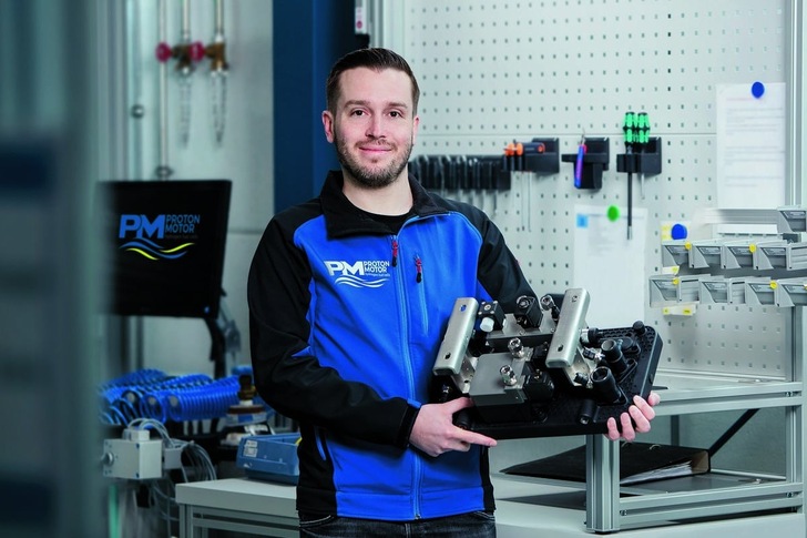
So that PEM fuel cells like the HyStack® 400 from Proton Motor Fuel Cell GmbH (see Fig. 2) can be operated without any problems, among other things, components for the hydrogen supply and water separation are required that meet the fluid control demands of the manufacturer and feature defined interfaces to the fuel cell stack module. Robert Baustädter (see Fig. 1), Fuel Cell Engineering division at Proton Motor, stated: “Such systems are essential for the functioning of the fuel cell, because they regulate the supply of hydrogen at the anode input and are also responsible for the safety shutdown. At the anode output, they must ensure gas purging and water separation.” Only then can several of these stacks (21.3 to 49.7 kW) be connected together and in HyShelter® (see fig. on p. 4) sold to customers as a turnkey container solution.

Fig. 2: The HyStack® 400 module from Proton Motor, Source: Proton Motor
The Bavarian company developed solutions for this together with Bürkert Fluid Control Systems, an expert for special fluidic components, whose materials are tailored to the special requirements of these areas of application and form the basis for a wide variety of system solutions. Among other things, compact blocks were developed for both anode supply and water separation, which are attached directly to the stacks using fluidic screw connections and require little installation space (see Fig. 1). „ The media adapter plates, which we have a partner produce using 3D printing, are more than just a mechanical interface. They are a multifunctional component that monitor the pressure and temperature of the individual stretches as well as ensure the proper tempering of the overarching system,” reported Robert Baustädter. The fuel cells are quickly ready for operation even in sub-zero temperatures.
Control valves in the anode block
In the anode block, a servo-controlled piston valve provides safety shut-off for the hydrogen supply. An integrated pressure sensor checks for the target pressure. As a redundant safety component, a pressure switch is also installed. To increase pressure and leakage safety, the plug and core guide tube are welded together. The shape and surface quality of the housing enable maximum flow values. The coils are pressed with chemically highly resistant epoxy.
A second valve – a direct-acting proportional valve – assumes the pressure control for the hydrogen. It is, with its integrated cut-off function, likewise tightly closing. For use in fuel cell systems, suitable plug-in (cartridge) and flange housings as well as magnetic coils with automotive connectors of protection class IP6K9K are also available.
Water and hydrogen separation
In fuel cell systems, the hydrogen introduced into the anode is never completely used up. In a recirculation cycle, the unused hydrogen is not wasted, but is fed back into the stack. At the anode output, the water separator with two integrated valves ensures, on the one hand, the flushing process of the fuel cell system and, on the other, the separating out of the water evolved in the stack during the chemical reaction.
For the two direct-acting plunger valves, the plug and core guide tube are welded together to increase the pressure and leakage safety. The sealing materials are adapted to the application, because the valves not only have to work precisely and reliably, but also have to be tailored to the specific area of application. With hydrogen, for example, the materials used must not become brittle and must not corrode when used with deionized water.
Robert Baustädter summarized: “For the HyStack 200 with outputs from 4 to 11 kW that is currently being developed, in principle the same fluidic systems could be used, just with smaller nominal valve sizes.”
Business operations of Proton Motor are shutting down
At the time of going to press, it was questionable what would happen next with the Puchheim-based company. Due to financing problems, employees are currently being laid off and new investors are being sought (see p. 7).
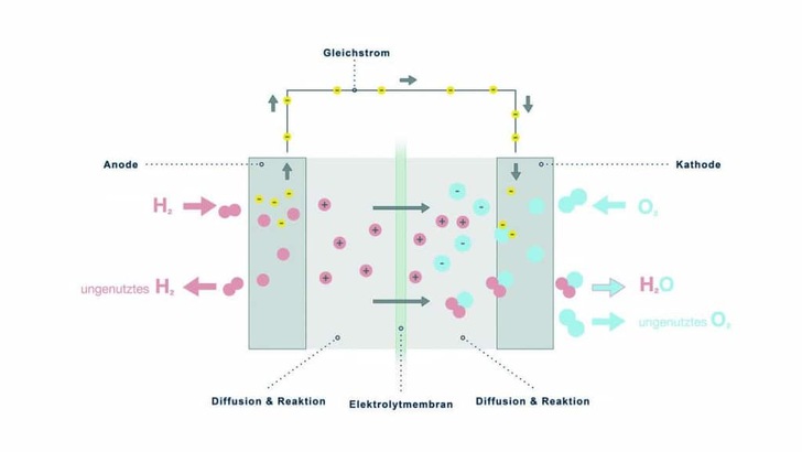
Fig. 3: Basic structure of a fuel cell, Source: Bürkert Fluid Control Systems
Authors: Sven Geitmann
Dominik Fröhlich, Jan Beranek, both at Bürkert Fluid Control Systems, Ingelfingen, Germany


